Methods
Scanning Tunneling Microscopy
Principle of the Scanning Tunneling Microscope (STM)
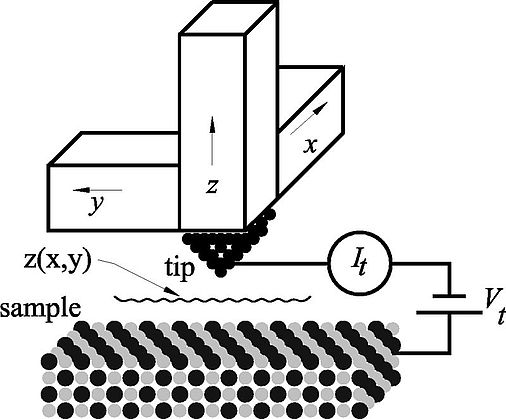
This Figure shows the general setup of a scanning tunneling microscope (STM): a sharp tip is mounted on a scanning device known as an xyz scanner, which allows three-dimensional positioning in the x, y, and z directions with subatomic precision. The tunneling tip is typically a wire that has been sharpened by chemical etching or mechanical grinding. W, Pt- Ir, or pure Ir are often chosen as the tip material. A bias voltage Vt is applied to the sample, and when the distance between tip and sample is in the range of several angstroms, a tunneling current It flows between the tip and sample. This current is used as the feedback signal in a z-feedback loop.
In the topographic mode, images are created by scanning the tip in the xy plane and recording the z position required to keep It constant. In the constant-height mode, the probe scans rapidly so that the feedback cannot follow the atomic corrugations. The atoms are then apparent as modulations of It , which are recorded as a function of x and y. The scanning is usually performed in a raster fashion with a fast scanning direction (sawtooth or sinusoidal signal) and a slow scanning direction (sawtooth signal). A computer controls the scanning of the surface in the xy plane while recording the z position of the tip (topographic mode) or It (constant-height mode). Thus a three-dimensional image z(x,y,It = const) or It (x,y,z = const) is created.
Atomic Force Microscopy
Principle of the Atomic Force Microscope (AFM)
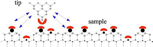
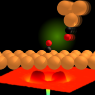
The AFM is similar to a STM, except that the tunneling tip is replaced by a force sensor. The figure on the left side shows a sharp tip close to a sample. Chemical short-range forces act when tip and sample orbitals (crescents) overlap. Long range forces (indicated with arrows) originate in the full volume and surface of the tip and are a critical function of the mesoscopic tip shape. The potential energy between the tip and sample Vts causes a z component of the tip-sample force Fts = ∂Vts / ∂z and a tip-sample spring constant kts = - ∂Fts / ∂z. Depending on the mode of operation, the AFM uses Fts or some entity derived from Fts as the imaging signal.
Unlike the tunneling current, which has a very short range, Fts has long- and short-range contributions. We can classify the contributions by their range and strength. In vacuum, there are short-range chemical forces (fractions of nm) and van der Waals, electrostatic, and magnetic forces with a long range (up to 100 nm). In ambient conditions, meniscus forces formed by adhesion layers on tip and sample (water or hydrocarbons) can also be present.
Therefore AFM faces four additional challenges:
- Attractive forces may cause an instability ('jump-to-contact')
- Potentially large long-range background forces add to weak short-range forces
- Measurement of weak forces (nano-Newton) is more prone to experimental noise than measurement of weak currents (nano-Ampere)
- Force-versus-distance relation is not monotonic, making distance control difficult
Frequency-modulation atomic force microscopy helps to overcome three of these four challenges. The nonmonotonic force-vs-distance relation is a remaining complication for atomic force microscopy.
The central element of a force microscope and its major instrumental difference from a scanning tunneling microscope is the spring which senses the force between tip and sample. For sensing normal tip-sample forces, the force sensor should be rigid in two axes and relatively soft in the third axis. This property is fulfilled with a cantilever beam, and therefore the cantilever geometry is typically used for force detectors.
Frequency Modulated Atomic Force Microscopy
Frequenzmodulations-Rasterkraftmikroskopie (FM-AFM)
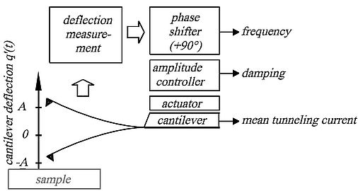
A cantilever with a sharp tip is excited in resonance by positive feedback, controling a constant amplitude A. For the free cantilever, the eigenfrequency is given by f0 = 2π ( k / m )0.5, k is the spring constant and m is the effective mass of the cantilever. Forces between tip and sample change the frequency f = 2π ( k + kts /m)0.5, where the tip-sample force gradient is given by kts. When kts is small compared to k and essentially constant within the tips trajectory to and from the sample, a frequency change results.
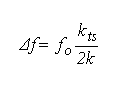
Forces cause a frequency shift, and with a feedback circuit adjusting the sample height such that Δf remains constant, an image is created.
"Classic" frequency-modulation-AFM with cantilevers with small spring stiffness k ≈ 20 N/m and comparatively large amplitudes A ≈ 10 nm enables routine-imaging at atomic resolution. However, theory shows that resolution enhancement is possible by using sub-nm amplitudes with stiff cantilevers. Minimal image noise δz is then proportional to
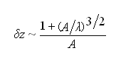
where λ is the range of the tip-sample forces. For chemical forces, λ ≈ 0.1 nm. Optimal resolution is expected for A ≈ λ.
Why didn't people use small amplitudes from the beginning?
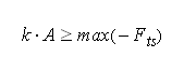
- The tip-sample forces disturb the cantilever´s oscillation. Jump-to-contact, e.g., is avoided if the restoring force that the cantilever exerts on the tip when it is deflected at amplitude A is larger than the sample force trying to pull the tip towards the sample:
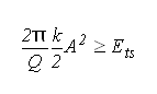
- Tip-sample forces are not conservative, i.e. the cantilever loses an amount of energy Ets on its way to the sample and back. This energy has to be supplied by the amplitude controller. The amplitude controller's task - keeping A constant - is easier if Ets is small to the intrinsic energy loss of the cantilever (given by its Q-factor). Thus, we have an additional (conjectural) stability criterion:
Operation with sub-nm amplitudes is thus only possible using very stiff cantilevers (k ≈ 1 kN/m). Traditional silicon cantilevers with such a large stiffness are usually not available, moreover they suffer from two additional disadvantages:
- The tips of microfabricated Si cantilevers point in a [001]-crystal direction - an unfavorable orientation.
- The eigenfrequency of Si-cantilevers varies strongly with temperature (-58 ppm/K).
A solutions to these problems offers the qPlus Sensor design.
qPlus Sensor
qPlus Sensor

Oscillators with low temperature drift are important in watch technology. Today, most watches utilize quartz tuning forks as time-keeping elements. Quartz tuning forks for watches are two coupled oscillators, housed in an evacuated metal case. Most of them come with an eigenfrequency f0 = 32 768 = 215 Hz.
We build cantilevers from these tuning forks by attaching one prong to a large-mass substrate and mounting a tip to the free prong, creating the "qPlus-Sensor". Its eigenfrequency is approximately 20 kHz (depending on the mass of the tip), and the spring constant of our favorite tuning forks (taken from Swatch-watches) is k = 1800 N/m.
The "qPlus Sensor" has following advantages:
- ideal stiffness
- superb frequency stability
- piezoelectric deflection readout is simple
- low power and low-noise
The advantages offered by high-stiffness, small-amplitude FM AFM have been demonstrated by experimental imaging of single atoms with "subatomic" resolution, i.e. structures within a single atom related to the orbital charge density have been resolved.
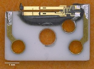
"qPlus Sensor" - a cantilever made of quartz for ultra-high resolution atomic force microscopy:
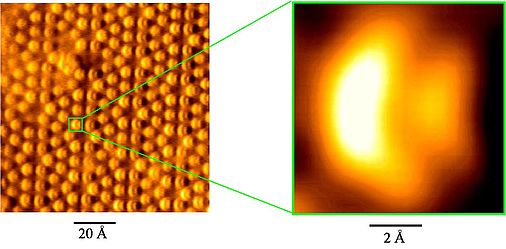
First experimental image (Si 7x7) showing internal atomic structures.
Webmaster - 02.11.2021 08:57